Infolinks

Monday, October 19, 2015

DIY Make Filter Subwoofer 16 Hz (Membuat filter subwoofer 16Hz)

Here is the other filter of subwoofer.
Filterization is under 16Hz. which is the lowest audio frequency that can heard by human.
Here is the schematic.
Filter subwoofer 16 Hz


The complete schematic can find here.

Good Luck
Thanks

DIY Make a Powerfull Subwoofer filter (Membuat filter subwoofer)

Here is my subwoofer project.
One of my subwoofer speaker is using this filter. with woofer (8ohm) speaker can transform to subwoofer system.
First time, you should make the filter to passing low sound and reject high sound.

Find the circuit here.

After finish make the filter, use power amplifier to drive the speaker. I only use 150watt OCL power amplifier.

Make two speaker in seri to get resistance 16 Ohm.
Don't make it in paralel, because the resistance is going to 4 Ohm, and it makes the speaker damage.

I use 8 inch woofer speaker by 2 pcs in one box.

the final subwoofer is like this. I placed in my car.
Finished Subwoofer
Just feel the power of low sound and enjoy.
If you don't get the lowest sound. kindly to double filter. the result is very powerfull, and change the speaker into real subwoofer speaker.

Good luck
Thanks

DIY Surround Sound Filter (Membuat sendiri filter surround)

Today, I'm going to make a surround sound filter.
This filter can make the sound is life. as like in concert.

The first think is we should have 4 speakers, which is placed on front 2 pcs and rear 2 pcs.
Let's see the schematic. find it here.

There is symbol in output. here is the description:
LF --> Left Front.
LR --> Left Rear.
RR --> Right Rear.
RF --> Right Front.

The placement is easy enough. find it here.

This combination can make the sound is surrounded us. the other side, the cost is very cheap.

For CTR and Sub is my next project.
The target is home theater 5.1

Just wait for my home theater project.

Good Luck.
Thanks

Make your own mini downloader AT89S51 using Parallel interface

Newest downloader is so practical and simple. But, it’s better for us to try mini downloader for AT89S51 using parallel port. The figure are displayed is illustrate only for the downloader is like. When you are change to another shape, it’s no problem. The IC is easy to get and find in electronic component shop. The making is easy, you don’t have to order the PCB which offered in  cm-square. Because the circuit is very simple.
Yup, you are right, you can download the circuit in the internet or a copy from your friend. For me, I tried as like published in the internet. The first time, I using parallel port which is include on the desktop PC.

The circuit is simple, just need x-tal 12MHz, capasitor 30pF. +5V VCC is use USB port.
Figure 1. Mini downloader

Figure 2. USB cable power
Component needed:

These circuit is tried for AT89S51/52 is always work. Although the connection is direct to LPT port behind PC. For the supply just connect to USB port, use USB cable and cut at the other side, and attach housing 2 pin.  

The schematic is here.

About LPT connector, use DB25 male. in order match on the desktop connector. 40 pin socket is for connecting the IC and any module. 40 pin are set as like the Micro pin configuration. The function is for plug and play without release the IC. And the software, you can download it in the internet or you can contact to my mail
yogisukardi@gmail.com, I’ll send it to you.
And for the training module, you can make it you self or use your imagination for the input and the output. The examples are going to describe on the next session. This time, we just making the downloader.
- 1 pcs mikro AT89S51
- 1 pcs x-tal 12MHz
- 2 pcs capasitor 33pF
- 1 pcs capasitor 10uF
- 1 pcs LED + resistor 100ohm.
- 1 pcs socket 40 pin male.
- 1 pcs DB 25 male.
- 1 pcs PCB make your own (etching your self

Good Luck

Wednesday, September 30, 2015

Make a Resistance check machine with Arduino (Membuat mesin pengecekan resistansi)

Salam Elektro

Today, I would like to share about how to make resistance check with arduino.
Kali ini, saya akan membagi bagaimana cara membuat pengecekan resistansi dengan arduino.

First time, prepare the material.
- Arduino Uno or other arduino. (I use Uno in my board).
- Potensiometer 5Kohm
- Switching power supply 12 volt
- Buzzer
- ULN 2003A
- Relay 12 volt
- LCD 16x2
- Connector banana female
- Pushbutton
- Power switch
- LED red and green
- Enclosure

Here is the fix machine

Hasil mesin pengecekan resistance


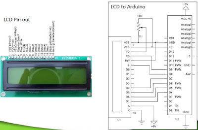
Connect wire from arduino to LCD, button and relay.
Here is the diagram block
Block diagram
Schematic diagram is here.


LCD guide
 
LCD guide pin out

 Schematic driver buzzer find it here.

Note of function

This machine can be set on some model, which is mean we can add some specification minimum and maximum.When the value is out of spec, then buzzer is  buzzing.
Mesin ini bisa di set ke beberapa model, yang mana maksudnya kita bisa menambahkan beberapa spesifikasi minimum dan maksimum. Bila nilai resistance berapa diluar spec, maka buzzer akan berbunyi.

Let's see the inside
Mari kita lihat hasil rangkaiannya walau tidak sebagus yang dipikirkan.
Bentuk dalam mesin
The Machine code is here.
Codingnya ada disini.

Good Luck
Selamat mencoba

Make digital clock with Arduino and RTC1302 (Membuat jam digital dengan Arduino dan RTC 1302)

Salam elektro

This time, I would like to share of Arduino programming. Make a digital clock with RTC 1302.
This program was modify from some reference program and mix in 1 shield.
I already try this and work fine in my shield.
If you have any question, kindly please insert in comment.
You can ask in english or Bahasa.

The code is here.
Library for RTC 1302 is here.

Good Luck

Thursday, May 7, 2015

Membuat program Jam digital pada LCD shield Arduino

Selamat siang

Ketemu lagi nih.
Kali ini saya mau coba share mengenai pngalaman baru dengan arduino.
Mungkin sudah terlambat kalau sekarang, tapi ya sudahlah. yang penting kita mau belajar, pasti ada jalan.

Kita mulai saja.
Perlengkapan yang dibutuhkan:
- 1 modul LCD shield V1.0
- 1 modul Arduino UNO (Clone juga bisa)
- Kabel data Arduino
- Power bank (untuk self power)

Arduino UNO R3
LCD Shield v1.0
Kedua modul di atas dihubungkan dengan cara di tancapkan antar pinnya.
Tampak samping
Tampak isometrik
Peralatan siap digunakan.
Buka software editor arduino.
Ketik programnya seperti di bawah:

Arduino Code is here.
Library for LCD is here.

Upload ke dalam modul.
kemudian hasilnya akan seperti di bawah:
Hasil jam yang telah selesai
Atur Jam, menit, detik dengan cara menekan tombol select.
kemudian masuk ke pengaturan jam, menit, detik. seperti gambar di bawah di bawah.
Mengatur jam
Mengatur menit
Mengatur detik
Gunakan tombol Up dan Down untuk menambah nilai datanya.
Setelah oke, tekan select sebagai tombol enter.

Jika ingin bisa di bawa-bawa. Gunakan Power bank sebagai power supplynya.
Namun, ya dengan catatan, harus setting ulang jam nya.
Berikut konfigurasinya.
Aktif dengan self power dari Power Bank
Selamat mencoba.

Tujuan pembuatan jam ini adalah untuk belajar bagaimana cara membuat bahasa pemrograman dengan bahasa C. khususnya pada arduino.
Sistem pada shield ini cukup unik, karena tombol yang digunakan hanya menggunakan 1 buah pin input.
yaitu pin A0 atau ADC0.
Metodenya adalah seperti sebuah potensiometer yang bisa berubah nilai resistansinya.
ini pun sama, jika tombol di tekan, maka nilai resistansinya akan berubah.
Seperti dibawah rangkaiannya.
Rangkaian tombol pada Shield LCD
Selamat mencoba.

Terima kasih


Thursday, March 5, 2015

Membuat Mini PLC berbasis AVR ATMEGA8


Akhirnya bisa nulis lagi. setelah lama berfikir mau nulis apa. Kali ini saya mau coba berbagi cara membuat mini PLC dengan menggunakan mikro kontroler AVR. AVR yang saya gunakan adalah ATMEGA8. Banyak sekali forum diskusi mengenai hal ini. Akhirnya saya coba membuat PLC ini. setidaknya cara kerjanya mirip dengan PLC aslinya. walaupun open source.
Perlengkapan yang digunakan adalah seperti dibawah:
- Downloader USB ISP. dongle. (Untuk mendownload)
- Mikrokontroler ATMEGA8 (lebih irit biaya karena I/Onya sedikit).

- Terminal biru ( Untuk input dan output).
- Relay 12 Volt (bebas berbagai bentuk)
- IC ULN2003 + socket
- Power supply 12V
- Regulator 7805
- Regulator 7812
- X-tal 13.5MHz
- Capasitor 22pF
- Resistor 10Kohm
- Cap 10uF 25V
- Push button
- PCB tentunya.
- EL817 optocoupler.
- LED secukupnya
- Software SinaProg (sebagai downloader).
- Software ldmicro (tempat membuat program ladder).
- Software PCB designer (software pembuat PCB).

Oke. kita coba mulai membuat.
Pertama-tama kita buat PCBnya dulu.
Berikut PCB yang sudah saya buat:
PCB Layout PLC Mikro
Layout Komponen
PCB yang saya buat menggunakan software PCB designer. software tersebut merupakan software pembuatan PCB secara manual. Tidak ada istilah auto route. jadi harus berhati-hati dalam menyambungkan jalurnya.
Berikutnya adalah waktunya print out PCB dan pemindahan layout ke atas PCB.
Cara pembuatan PCB sudah saya jelaskan di artikel saya terdahulu.
Layout di atas papan PCB polos

Waktunya melunturkan lapisan tembaga yang tidak diperlukan.
pastikan jalur tidak ada yang short satu sama lain.
Lakukan pembersihan, kemudian bor lubang komponen dan solder.
Berikut hasil jadinya.
Tampak atas

Tampak Bawah
 Waktunya pengetesan dengan LDmikro.
 LD Mikro
Hasilnya LED di output menyala.
Mikro ini memiliki memiliki Input 13 pin dan output 7 pin dengan relay.
Board ini bisa menggantikan PLC mini pada umumnya yang kisarana harganya sampai 3 jutaan bahkan lebih.

Selamat mencoba, semoga bermanfaat.
Terima kasih